A Thousand Jobs Prior to Launch.
- Chris Leigh-Jones
- May 17, 2023
- 3 min read
Updated: May 17, 2023
We all create parallels in our lives. For me, there is a strong parallel between the boat-building process and creating a custom home. The big stuff happens quickly and creates a dramatic change. So laying the keel, turning the hull, installing the top structure .... all quite exciting. Then you fall into a seemingly black hole of detail. Wiring schematics, aerial layout, COLREGS compliance, ducting runs ..... This takes time, patience, and cooperation across often competing disciplines. Thus, we, by necessity, put on our big girl pants and dived into the details of Vanguard's build.
So this morning, I woke to a list of requests from the Yard.
What is the connection schematic between the Esco Power clutch drive and the Praxis I/O Module?
I must understand the Byte allocation on the PGN list for the J1939 engine CAN Bus interface. (Did you like that one? Seriously, it's 5.30 a.m.!)
Can you tell me which VHF Aerial we can usefully sacrifice as we have redundancy issues?
PGN is an 18 bit subset of the signal Identification under an SAE J1939 CAN Bus protocol. It identified the signal and a number of features of that signal. The more familiar NMEA 2000 data communication protocol uses a similar system.
Then I went and had more coffee. If anyone is considering building their own Explorer Yacht, expect to be at the "Youtube School of Education" and at least grasp some pretty esoteric system features. Learn them now or when they go wrong; no help is available.
The day though, did improve.
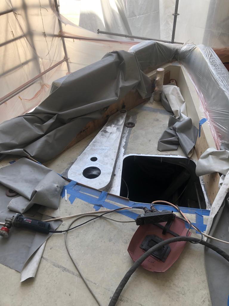
We saw the modifications made to raise our windlass so that the mooring lines ran fairly in tko the capstan drum. We also saw the start of the forepeak hatch coaming. Both needed completion before painting.
We also apprved the final mounting arrangement for main Helm MFD display screens. the initial arrangement (right) tended to appear restrictive and blocked the view, the final (left) was much more open.
The first (right) solid boxed mounting was rejected as obscuring he view.The second (left) consisted of frames to hold the MFD screen in place. Much less obtrusive and was approved.
On the subject of a painting, we test-fitted all lights and navigation equipment to the new instrument mast before sending it to the paint shop—an opportunity also to check sight lines and the overall schema. Plans worked in most instances though we did spot the opportunity to mount Cell System 4G aerials higher to improve reception. VHF whip Arials were also rationalized from 4 to 3 and set higher and away from potential interference (two for ICOM VHF, one for AIS systems). Placing these components is a struggle between aesthetics and making sure that each component can operate free of interference that itself operates in three dimensions. I appreciate it when the local equipment agent (in this instance, Furuno) is also the installer and brings with them a wealth of knowledge no one else has the time to learn from scratch.
Lights positioned as per COLREGS, Radar, One Web, Certus operating cones have free line-of- sight. VHF aerials and SatCom are free from interference.
Two final points to contribute before we close out this blog.
1. Tuesday saw an awful fire at Damen Shipyard in Antalya, luckily, no one was hurt, but it destroyed the shed. In it was stored bulk fiberglass resin and destroyed several completed hulls. Luckily no one was hurt though it's a dramatic illustration that fiberglass may not be the best choice when working a hull far away from help.
2. We also received two photos of the recently splashed Arksen 85 hull. Photos were geo-located near Southampton in the UK.
A beautiful piece of design, if I may say so. My wife, Sebrina, wants one, and we look forward to bumping into her on our respective journeys!
Chris Leigh-Jones


