This our final Blog for 2022 following a visit to Naval Yachts. With Christmas now fading, my wife and I would like to wish you all a prosperous and healthy New Year. It will be an adventurous one for us as we take our last son out of school and begin our journey. Until then, we have to complete the build!
Vanguard's build is now coming along well; we can judge progress by the type of questions the yard asks.
This morning's salvo was a series of questions and suggestions for the instrument mast. Radar, Aerials, Lights, GPS, AIS ...... Rather than a knee jerk type answer, it was time to become a little analytical rather than simply judging on the prettiest version. This is how we approached the issue.
Design Criteria
The mast provides several functions and form, in this instance, must follow function. From holding the lights high to supporting the radar, communications aerials to the satellite, and flying the various courtesy flags. Each one of these has some unique requirements. To decide on the final configuration, we first listed what each requirement and it's constraints as repeated below:
Navigation lights are required to satisfy COLREGS requirements; high up is good, and the Port and Starboard lights need to be separated as much as possible.
Radar - we have 2 X Band radars to install. Each needs clear sight for 360 degrees with minimal interference from physical structures that reflect the beam. Additionally, they need to be high enough that the beam does not impinge on the forward flybridge roof.
FLIR (illumination laser and IR and low light visible cameras) - need to be placed with a view of the bow and as high as is practical.
Communications aerials - the flat aerials need to be out of the radar beam and with a clear sight of the sky within a 53-degree vertical cone.
VHF/SSB - whip aerial needs to be as high as possible and separated.
Lightning arrestor - need to be the highest of all.
AIS/GPS/Fluxgate - need to be out of the way of the radar.
Courtesy flag - we need to keep this up in the air!
The Design Process
So how did this process unfold?
| First Design | Final Design |
Nav Lights | yes | yes |
Radar | no | yes |
FLIR | no | yes |
VHF/SSB Whip | yes | yes |
Comms Aerial | no | yes |
Lightning Arrestor | no | yes |
AIS/GPS/Fluxgate | yes | yes |
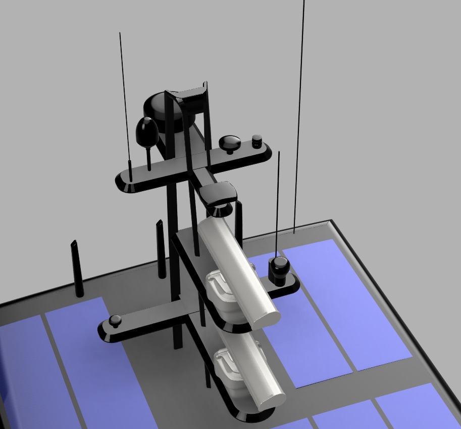
The renderings below illustrate the first design drafted at the yard. Looks apart, we examined this against our requirements. The FLIR and Lightning arrestor were missed so an obvious fail there. The failure was ours in not being specific about just what equipment was to be fitted. That's is easily remedied. The Comms aerial was in part correct (Sailor 4300) but has omitted the OneWeb system, so we needed to correct that also.
The major failure of this design is provision for the radar. We have primary and backup X Band Doppler Radar. They do not operate coincidentally. The mast is close to the rotating transmitter on this version and produces a substantial shadow to either Port or Starboard creating a blind spot in that location. Additionally, the beam would impinge on the flybridge roof (horizontal beam angle is 22 degrees inclusive not as shown in the illustration) resulting in an additional blindspot showing forward of the bow.

Sat Comms Aerials have recently improved in weight and especially size. The new square flat units use a solid state phased array to track the various satellite clusters.
These hand-off the signal from one aerial to another as the satellites move out of the detection cone (in our case 53 degrees or 106 included). To operate correctly there must be a clear view of the sky within this cone as shown in the enclosed illustration. We rearranged the solar panel layout to allow space for the Oneweb aerials at the front of the flybridge, clear of other obstructions and easy to access.
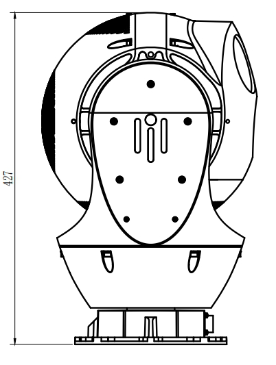
FLIR - this is a large device, an ex military unit that we bought on an impulse.
Height is useful but were also concerned with vibration, especially considering the optical and electronic magnification capabilities. Bigger picture, more obvious shake regardless of the subsequent added stabilization. We decided to secure the camera on the front of the flybridge deck/helm station roof.
This means we have excellent forward vision but its limited to a 200 degree arc. Given we are more concerned about what is in front than behind, we can live with the compromise.
We also messed around with the positioning of the aerials. Two VHF aerials were combined with a splitter so we can manage signals for both VHF and AIS from the single unit. The third was moved to a lower position so that the two aerials did not interfere with each other (like a. torch and mirror in their own spectrum). The SSB aerial is 4m, we positioned it on the flybridge pending later advice from the installer. There are three small vertical aerials on the aft edge of the flybridge roof. One of these is WIFI booster that pick up signal from the marina or wherever available and boost it. The remaining two are boosters for the onboard WIFI system on Vanguard herself.
Lastly there was some concern of weight and windage being placed so high up on the vessel. We opted for an open lattice mast structure to minimize both. The basis is illustrated above though this design still requires detail engineering. No one is claiming credit for this as its similar to other Artnautica, FPB and Arksen designs. By removing a few retaining bolts, the mast can be lowered for maintenance.with assistance from the windlass capstan and a flew blocks.
Chris Leigh-Jones
My last paragraph is a constant thought when developing ideas for Vanguard, irrespective of the form of a design, can it be maintained thereafter and if so how? My introduction to this came as an apprentice. I submitted a simple fabricated gearbox design and was informed that although the design itself would work, it needed a suicidal Elf to fabricate it. All the weld symbols were on the inside!


